

Requirements
- Visual Studio.
- Arduino IDE.
- Connecting wires (10 numbers or more).
- Breadboard.
- DC motors can run by just 5 volts power supply (2 numbers).
- LED light (1 number).
We expect advancement in our day to day life. That is why I have thought of implementing a voice control technology using Arduino to take control of the electrical appliances at my home. Hence, in this article, I will explain how to create an application that helps you control the devices in your home, with your voice commands. So, to make it simple, I will explain how to connect a door that can be opened and closed and a fan along with a light that can be turned on and off, using the voice commands. Click on the following links to know more about home automation using voice controls.
Step 1 Programming the Arduino
- Open the Arduino IDE if already installed (or download and install it from this link).
- Now, open the IDE and enter the following code in it.
- char incomingdata;
- void setup() {
- pinMode(2, OUTPUT);
- pinMode(4, OUTPUT);
- pinMode(12, OUTPUT);
- pinMode(13, OUTPUT);
- Serial.begin(9600);
- }
- void loop() {
- incomingdata = Serial.read(); {
- if (incomingdata == 'a') {
- digitalWrite(2, HIGH);
- } else if (incomingdata == 'b') {
- digitalWrite(2, LOW);
- } else if (incomingdata == 'c') {
- digitalWrite(4, HIGH);
- } else if (incomingdata == 'd') {
- digitalWrite(4, LOW);
- } else if (incomingdata == 'e') {
- digitalWrite(12, HIGH);
- digitalWrite(13, LOW);
- delay(3500);
- digitalWrite(12, LOW);
- } else if (incomingdata == 'f') {
- digitalWrite(12, LOW);
- digitalWrite(13, HIGH);
- delay(3500);
- digitalWrite(13, LOW);
- }
- }
- }
- In this program, I have used a delay of 3.5 seconds in the last two conditions. This is because of the length of the door which I have used in my prototype. You can change the delay length according to your prototype.
- Save this sketch at any location and verify the code.
- Now, connect your Arduino board and upload this sketch into the board.
Step 2 Programming in Visual Studio
- Open Visual Studio and create a new Windows Form application with any name you want.
- Once you have created a new form application, open the designer window of Form1.
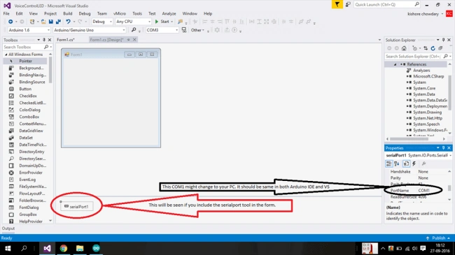
- Now, from the tool box, drag and drop the SerialPort tool into the form1.
- This will help your program communicate with the Arduino board.
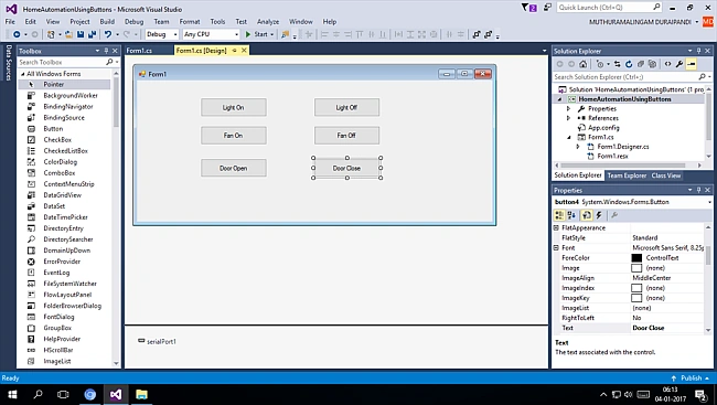
- Now, drag and drop six buttons in the form to make use of them for controlling the lights and fan.
Step 3 Creating buttons
- Drag and drop six buttons in the form.
- Name them as LIGHT On, LIGHT Off, FAN On, FAN Off, DOOR Open, and DOOR Close.
- Once you finish these all, the form looks like below.
Step 4 Writing code for controlling and using buttons
- The controls will work as they are if you build your prototype by connecting a DC motor with a small fan wing to work like a fan and another DC motor with a door which can be moved up and down like a shutter door and also an LED which can work as a light.
- Remember again that you are building a prototype for an automated house and not a real house.
- Double click on the "Light On" button. You will get to a coding page. There, you must add a small piece of code for the button click event.
- Add the button click event code for each and every separate button.
- Have a look over the code.
- using System;
- using System.Windows.Forms;
- namespace HomeAutomationUsingButtons {
- public partial class Form1: Form {
- public Form1() {
- InitializeComponent();
- }
- private void button1_Click(object sender, EventArgs e) {
- serialPort1.Open();
- serialPort1.Write("a");
- serialPort1.Close();
- }
- private void button6_Click(object sender, EventArgs e) {
- serialPort1.Open();
- serialPort1.Write("b");
- serialPort1.Close();
- }
- private void button2_Click(object sender, EventArgs e) {
- serialPort1.Open();
- serialPort1.Write("c");
- serialPort1.Close();
- }
- private void button5_Click(object sender, EventArgs e) {
- serialPort1.Open();
- serialPort1.Write("d");
- serialPort1.Close();
- }
- private void button3_Click(object sender, EventArgs e) {
- serialPort1.Open();
- serialPort1.Write("e");
- serialPort1.Close();
- }
- private void button4_Click(object sender, EventArgs e) {
- serialPort1.Open();
- serialPort1.Write("f");
- serialPort1.Close();
- }
- }
- }
Step 5 Giving the connections in the breadboard
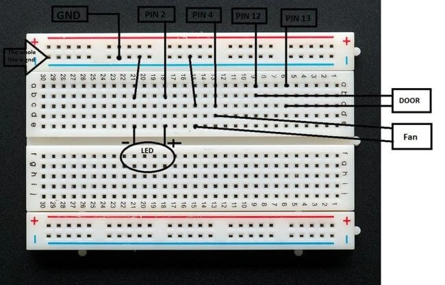
- According to the program, I have used pin 2 of the Arduino for light, pin 4 for the fan, and pin 12, 13 for the door.
- Since the door needs to move in both directions, we need to make the dc motor of the door run in both directions.
- Hence, the door is given with two-pin connections.
- Take a ground connection from the Arduino and connect it to the breadboard.
- Take pin 2 and connect it to the LED along with the ground connection.
- Take pin 4 and connect it to the DC motor along with the ground connection which will act as a fan.
- Take pins 12, 13 and connect each of them to one end of the motor so that it can run in both directions.
- Take a look over the image for clarification.
Working of the setup
- When you click on the Light On button, lights will get turned on and when you click on the Light Off button, lights will get turned off.
- When you click on Fan On button, the fan will turn on and when you click on the Fan Off button, the fan will turn off.
- When you click on the Door Open button, the motor of the door will rotate in a direction and then turn off after a few seconds.
- When you click on Door Close button, the motor will rotate in another direction and then turn off after a few seconds.
Final step
- If you are unable to build a simulated model, you can just give connections for the LEDs and the DC motors and check the output.
- Here, for the door, the motor will just rotate in bi-directions. Hence, you need to create the door such that it can move up and down.
- Once again, check all your code and the connections.
- Now, click on the buttons and check the output.
Ishan ShahPosted Mar 30, 2017, 7:29 AM
Can you please update about Hardware requirements? Does it require RaspberryPi?
Avnish KumarPosted Jan 27, 2017, 7:13 AM
Nice article.....................................................................
Joe WilsonPosted Jan 5, 2017, 1:45 PM
Thank you very much for sharing.
Humayun Kabir MamunPosted Jan 5, 2017, 3:57 AM
Very helpful article about IoT...