

Introduction
Arduino
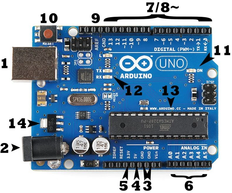
The above is the simple Arduino Board which does miracles. Let's understand the points mentioned in the diagram and their usage!
- 1 - USB Jack
This is the connecting female port, where the cable gets inserted in order to set a connection to the computer to have the IDE accessible and upload the programs.
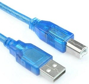 Usually, it is a 2.0 USB port. The input and the output passage happens through this, we can consider this to be the starting point of the Board. Usually, the voltage acceptable is,Input Voltage (acceptable)- 7-12VInput Voltage (limit)- 6-20V
 - 2 - Power Jack
As the name suggests, it is the external power supply. But be careful while using this, use a multimeter to check for the acceptable limit of power to be transferred to the board in order to avoid a short circuit.
- 3 - GND Pins
The grounded pins used to connect the jumper wires to have a grounded circuit. Usually, when we see the connection we will realize that GND pins are considered as the negative supply.
- 4 - 5V Supply
This is the point used to have the breadboard 5V supply in order to power the circuit, which we will check out in a few moments.
- 5 - 3.3 V supply
This is the point used to have the breadboard 3.3V supply in order to power the circuit. Same as the 5V but based on our circuit requirement we can also use this in case we are missing resistors.
- IOREF:-Though not numbered in the diagram, this is an interesting port in the board, which provides the voltage ref. with which the microcontroller or the Arduino board operates.
- Vin:-As discussed above the external supply to the board, to pass the voltage to the circuit (external), we can use this port.
- IOREF:-Though not numbered in the diagram, this is an interesting port in the board, which provides the voltage ref. with which the microcontroller or the Arduino board operates.
- 6 - Analog Input Pins
These are the analog points in the board, which would help convert analog inputs to digital. Usually used to read analog signals.
- 7,8,9 - Digital Pins
The digital pins provide the circuit for the uploaded code to connect (layman terms). Used for digital I/O.
- 10 - Reset Button
It is self-explanatory, used to reset the microcontroller or the board.
- 11 - ON
When connected to the USB, this green led lights up to let us know the board is powered.
- 14 - Voltage Regulator
The voltage regulator supplied to the Arduino board.
- 12 - RX-TX LEDs
These are the LEDs that light up when the code or the program is successfully uploaded to the microcontroller. This is the practical implication I have come across so far.
For more info on the pins please refer to Arduino Pins.
So this is it about the Arduino board, a brief summary I would say! There is much more to this. Please refer here.
Some Prerequisites
Here are some pre-requisites required to learn and start on your work with the Arduino. After you get the Arduino board from the market, the next job is to install the Arduino IDE on your system in order to interact with the microcontroller.
To install the IDE visit the link: Arduino IDE Download. Here, you get a list of OS where you can install it, this proves it is cross-platform! :O Wow!! Another great feature.
After the installation, you need to connect the USB jack to the computer via the jack cord and get the Arduino connected.
The IDE somewhat looks like this,
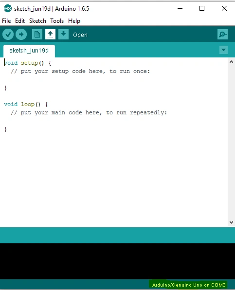 Mark the highlighted portion below, it says Arduino UNO on COM3. COM3 is a serial port id, which suggests we select the Board connection on COM3 port.
For getting on with MAC, please follow the link here.
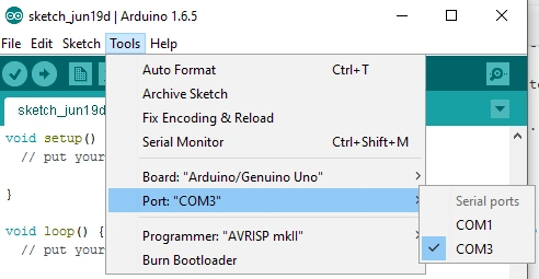
The selection is to be done under:
Tools-> Port-> "Select",
Mark the highlighted portion below, it says Arduino UNO on COM3. COM3 is a serial port id, which suggests we select the Board connection on COM3 port.
For getting on with MAC, please follow the link here.
The selection is to be done under:
Tools-> Port-> "Select",
 The default code as you see goes like:
Pretty simple to understand. It first does the setup and then the loop code gets executed in order to perform the main task you have configured. There are many sample programs built-in with the code, which we can find under:
- void setup()
- {
- // put your setup code here, to run once:
- }
- void loop()
- {
- // put your main code here, to run repeatedly:
- }
- // the setup function runs once when you press reset or power the board
- void setup()
- {
- // initialize digital pin 13 as an output.
- pinMode(13, OUTPUT);
- Serial.begin(9600);
- }
- // the loop function runs over and over again forever
- void loop()
- {
- digitalWrite(13, LOW);
- // turn the LED on (HIGH is the voltage level)
- delay(1000);
- // wait for a second
- digitalWrite(13, HIGH);
- // turn the LED off by making the voltage LOW
- delay(1000);
- // wait for a second
- }
- Bread Board
The board is familiar to all electrical or engineering students also.
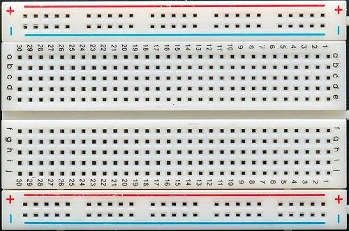 Still, let's have a brief explanation of this. As we see in the image, + symbol, means the voltage connection is to be done to this port. The entire line, column-wise, is connected. Every hole in the plus column is connected internally. You can use a multimeter to check and verify the breadboard.Same applies to the - symbol column. But, this is usually used for the grounded pins connection from the Arduino. The a,b,c,d.. columns are used to connect the LEDs and the resistors, which we will see in a while. Unlike the +/- these are connected internally ROW-WISE.
 - Jumper Wires
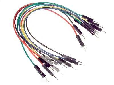
These are the connecting wires to be used in order to connect the Arduino and the breadboard ports. They are cheap and reliable as well. They look like,
- A few LEDs and resistors.
Next is to design our circuit, which looks like,
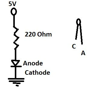 The above is the basic breadboard connection circuit. I will give a pictorial image of the entire circuit connection. In this article, I will be sharing how to take user inputs through the Serial port and use it to light the LED on and off. The circuit connection looks like below,
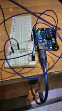
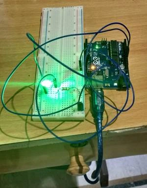 The connection diagram is below,
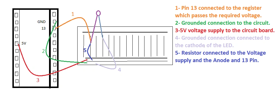 The above diagram is a reference. For any doubts, you can add your queries related to the connections. As you have seen, I have used Pin 13 to connect the Arduino program to the Breadboard. That is the programming uploaded that will be used to manipulate the LED on/off via Pin 13. Let's have a look at the code involved,
Thus the above code is simple to understand. We have used the Serial port to track the user input, which is a part of the Arduino IDE.
- int userInput = 0;
- // the setup function runs once when you press reset or power the board
- void setup()
- {
- // initialize digital pin 13 as an output.
- pinMode(13, OUTPUT);
- Serial.begin(9600);
- }
- // the loop function runs over and over again forever
- void loop()
- {
- if (Serial.available() > 0)
- {
- // read the incoming
- byte: userInput = Serial.read();
- // say what you
- got: Serial.print("Received Input: ");
- Serial.println(userInput, DEC);
- }
- if (userInput == 49)
- {
- //As checked through, if 1 is pressed, the result comes to be 49 based on the ASCII code
- digitalWrite(13, HIGH);
- // turn the LED on (HIGH is the voltage level)
- delay(1000);
- // wait for a second
- } else
- {
- digitalWrite(13, LOW);
- // turn the LED off by making the voltage
- LOW delay(1000);
- // wait for a second
- }
- }
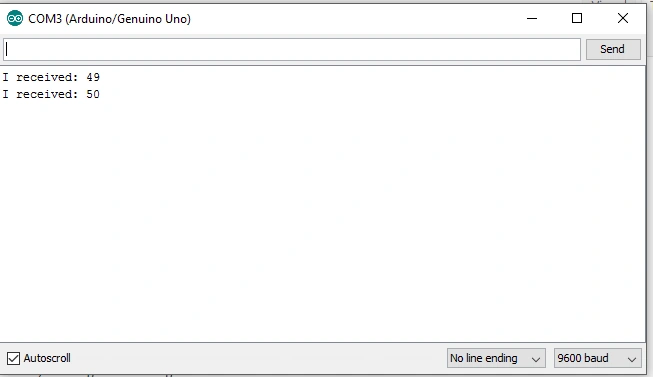
Here, the user adds the input, and our code checks, if 1 with ASCII code 49, is hit then the LED lights ON and if any other key is pressed the LED goes OFF.
Santhakumar MunuswamyPosted Jun 25, 2016, 1:03 AM
Thank you for nice article. Keep it up
Prasanna MuraliPosted Jun 21, 2016, 9:31 PM
Nice one...
Kuppurasu NagarajPosted Jun 21, 2016, 12:40 PM
Nice Sharing..
Debasis SahaPosted Jun 21, 2016, 12:48 AM
Good One..
Dinesh BeniwalPosted Jun 21, 2016, 12:45 AM
Good start Suraj ;)
Praveen SreeramPosted Jun 21, 2016, 12:14 AM
Very nice.. Thanks.. Could you please IM me the link where I can purchase the Arduino Board?